Arduino
Nov 24 2021
Arduino is an open-source electronics platform based on easy-to-use hardware and software. Arduino boards are able to read inputs - light on a sensor, a finger on a button, or a Twitter message - and turn it into an output - activating a motor, turning on an LED, publishing something online.
- Open-source Electronics prototyping platform
- Uses a “microprocessor”/”microcontroller”
- Programmable in language similar to C
- Implements many inbuilt functions
- Multiple sensors available for use
- Lots of support online - very popular
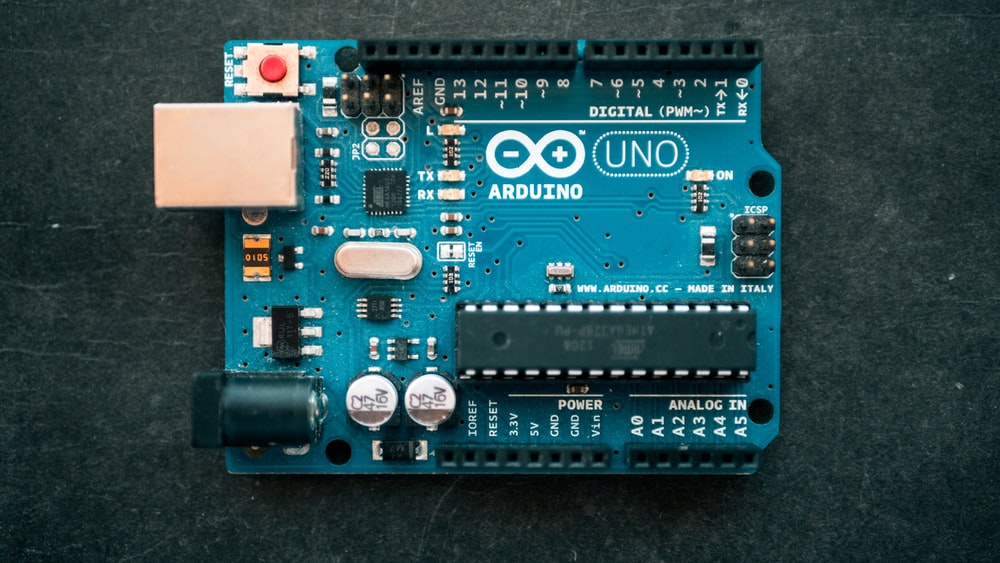
There are different Arduino Boards available in the market like Arduino UNO (R3), Arduino Nano, Arduino Mega (R3), etc. We will focus on Arduino UNO R3 in this tutorial.
Programming Arduino
- Arduino uses its own IDE (Integrated Development Environment) to write programs.
- Setting up and programming Arduino : Arduino
Arduino UNO
Arduino pins
If you want detailed info on any of the pins , you can visit here:
robotics backend/arduino-uno-pins
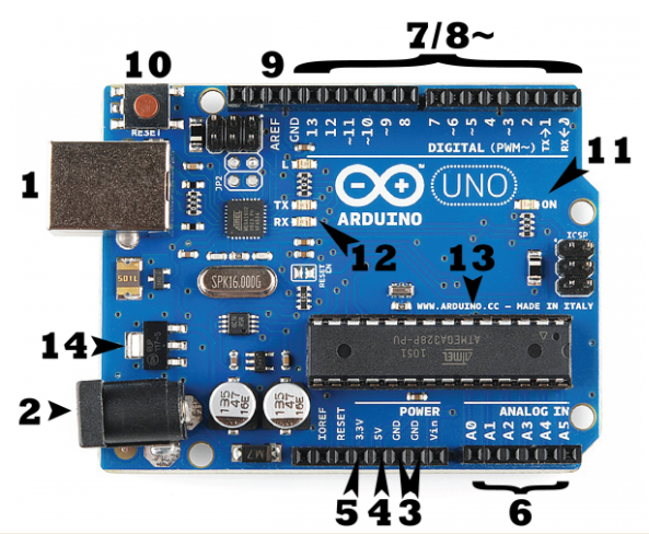
1 - USB CONNECTOR
2 - POWER JACK
3 - GROUND PINS
4 - 5V PINS
5 - 3.3V PINS
6 - ANALOG INPUT PINS
7/8 - DIGITAL PINS- out of the 14 Pins, 6 can be used for PWM (denoted by ~)
9 - ANALOG REFERENCE
10 - RESET BUTTON
11 - POWER LED
12 - TX/RX LEDS
13 - ATMEGA328P
14 - VOLTAGE REGULATOR
Power Pins
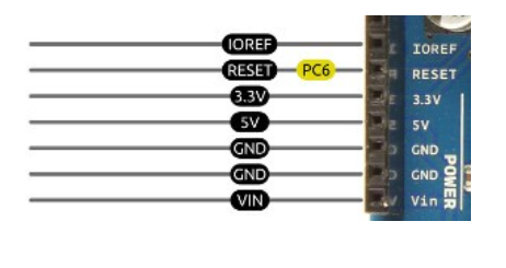
- Vin is the input voltage to the board when it’s using an external power source (as opposed to 5 volts from the USB connection or other regulated power source from the power jack)
- You can supply voltage through this pin(from external circuitry), or, if supplying voltage via the power jack, access it through this pin.
- This is how you power the board when it’s not plugged into a USB port for power. Can accept voltages between 7-12V(But the voltage is regulated to a maximum of 5V)
LEDs
- Pin 13 LED: The only actuator built into the board. Useful for debugging, since the LED is in-built and hence reliable in terms of connections.
- Power LED: Indicates that the board is receiving power. Useful for debugging.
- Reset button: Resets the ATmega microcontroller.
- TX and RX LEDs: Indicate communication(send/receive) between the board and the computer. Flicker rapidly during sketch upload as well as during serial communication. Useful for debugging.
USB Port
- Used for the board, and most importantly, uploading your sketches to the board.
- Also used for communicating with the sketch (via Serial.println() etc).
Digital Pins
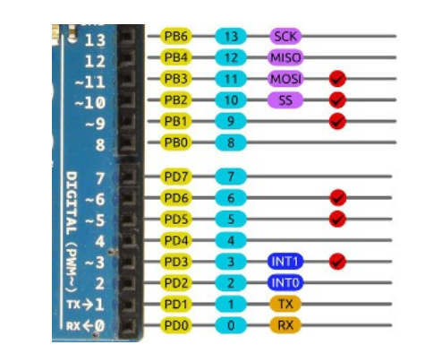
Digital Input/Output pins(0,1 are serial in/out) are numbered from 2-13
High(5V) or Low(0V)
Digital reading pins ( for input V < 0.8 => low; V > 2 => high)
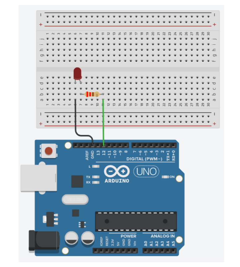
Arduino LED:
Example 1:
Let’s make the LED blink, which means that we are going to :
- Power in the LED
- Wait
- Power off the LED
- Wait
- Go back to 1
See the code here : Example1
digitalWrite(Pin_no, HIGH/LOW);
HIGH sets the pin to give a 5V (high) output while a low sets the pin to give a 0V output.
Only to assign the value to the output pins.
digitalRead(Pin_no);
Gives the reading of the digital input pin as a high or a low.
PWM Pins
PWM enabled pins(3,5,6,9,10,11) can also be used as Analog Outputs (represented by ~)
analogWrite(LED_PIN, n); n can take values from 0 to 255.
In the Example1 replacing line digitalWrite(LED_PIN, HIGH); with analogWrite(LED_PIN, 102); will cause 102/255 ie. 40% of maximum voltage( 5V) across circuit.
(can be used to change the brightness of the LED in this example)
Example 2:
Let’s make the LED fade in (which means the brightness will slowly increase until the max), and then fade out (brightness will slowly decrease), so we can create a nice effect with the LED.
See the code here : Example2
Analog Pins
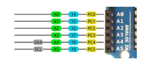
**analogRead(Pin_no);
**Reads the input from the analog pins marked as A0,A1...A5 on the arduino board. This reading is a 10 bit value (0-1023).
Let's say Arduino is reading 2V.
2V is 40% of 5V (Vcc). In your Arduino program, you will then get the value 409 ( 40% of 1024 ). From this value, you can easily reverse the computation and get the information about the voltage that was applied.
Serial Communication
Serial is used for communication between the Arduino board and a computer or other devices. All Arduino boards have at least one serial port (also known as a UART or USART). It communicates on digital pins 0 (RX) and 1 (TX) as well as with the computer via USB. Thus, if you use these functions, you cannot also use pins 0 and 1 for digital input or output.
**Arduino Serial port and Print Commands:
**See the example here : Example 3
Open the Serial monitor ( on top right corner)
Serial.begin(baud_rate);
Sets the data rate in bits per second (baud) for serial data transmission. Settable to 300, 600, 1200, 2400, 4800, 9600, 14400, 19200, 28800, 38400, 57600 or 115200 baud rate defined here and that selected on the serial monitor should be the same.
Serial.end();
Disables serial communication, allowing the RX and TX pins to be used for general input and output.
if(Serial);
Indicates if the specified Serial port is ready.
Serial.available();
Get the number of bytes (characters) available for reading from the serial port.
Serial.read();
Reads incoming data
Serial.print(j);
print on the same line
There are many serial functions that have not been covered in the previous segment, but they are important for some specific uses.
https://www.arduino.cc/en/reference/serial
**Reading data from serial monitor :
**Example 4 : Tell the Arduino how many times you want to blink LED
See the code here: Example 4
Interrupt Pins
Purpose - Stop the continuous progress of an activity or process.
Interrupts triggers a function inside the Arduino code. This stops the main execution of your program. After the triggered function is done, the main execution resumes.
Digital Pins 2, 3 are Interrupts pins.
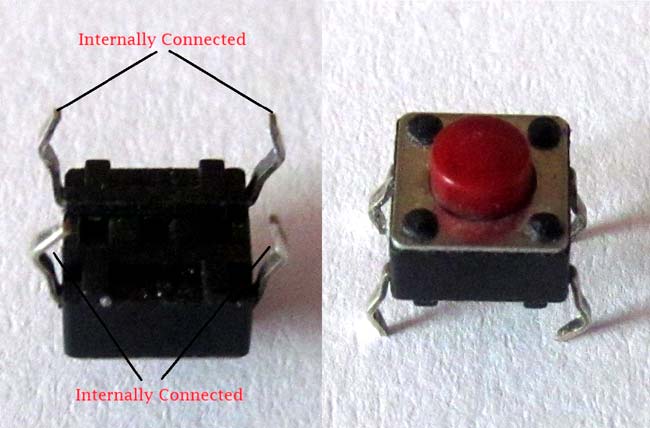
Before going through the example, lets introduce the push button. You should notice which pins are internally connected and which are not.
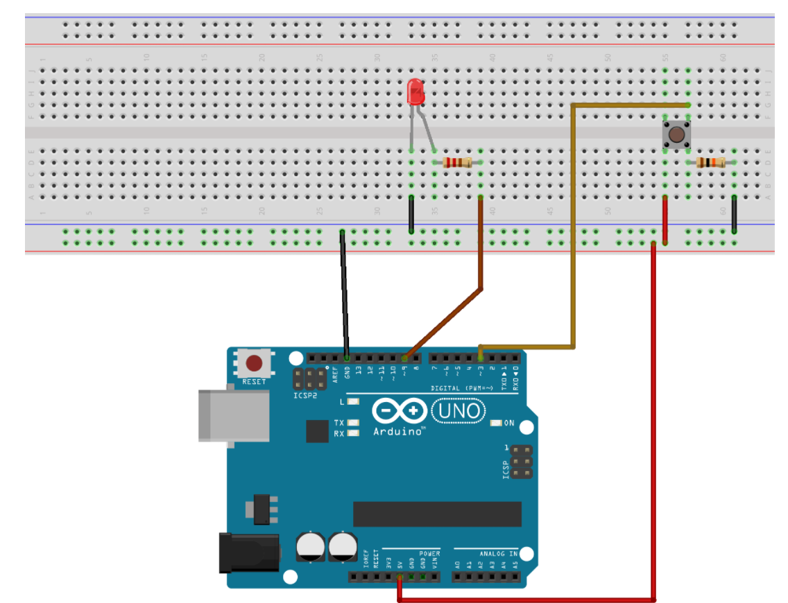
Example 5: The goal of the Example is to change the state of a LED when the the user presses a push button.
Part 1 : Arduino code without interrupts
See the code here : Example5_Part1
Part 2 : Arduino code with Interrupts
See the code here : Example5_Part2
Note : Make the interrupt function as fast as possible, because it stops the main execution of your program.
Volatile Variables :
If you modify a variable inside an interrupt, then you should declare this variable as volatile.
The compiler does many things to optimize the code and the speed of the program. This is a good thing, but here we need to tell it to “slow down” on optimization.
For example, if the compiler sees a variable declaration, but the variable is not used anywhere in the code (except from interrupts), it may remove that variable. With a volatile variable you’re sure that it won’t happen, the variable will be stored anyway.
Note that only variables that are used inside and outside an interrupt should be declared as volatile. You don’t want to unnecessarily slow down your code.
If you want to get deeper into Interrupt pins, check this out : arduino-interrupts
Peripherals
Arduino supports multiple peripherals like:
- Ultrasonic Sensor
- LCD
- Bluetooth
- Pressure Sensor
- Accelerometer/Gyrometer
- RTC module
- SD card
- LDR sensor
- Temperature sensor
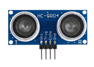
Ultrasonic Sensor
- This sensor sends out pulses from T, which bounce off from the object and R receives them.
- When the receiver gets the U.S. pulses, it generates a high signal. We get the time difference between the pulses which is used to calculate the distance
- The speed of sound is approximately 341 meters (1100 feet) per second in air.
- Distance = (Time x Speed of Sound)/2
Useful Function:
pulseIn(Pin_no, HIGH);
Gives the time in milliseconds from the time this command is initiated until Pin_no gives a HIGH pulse.
Sample:
- Initialise variables before setup()
- Sets the data rate of data received from the board using Serial.begin() and sets the trig pin to OUTPUT and echo pin to INPUT.
- First three lines of loop() send out a trigger pulse on the trig pin to cause the sensor to emit an ultrasound pulse.
- pulseIn(echo, HIGH) records the time after which the echo pin receives a HIGH pulse.
- Data is converted into distance in cm and printed to the Serial monitor.
Exercise:
How to measure distance using Ultrasonic sensor HC-SR04 - Link (Error in pin mapping)
Note:
TRIG connection of the sensor attached to digital pin 12
ECHO connection of the sensor attached to digital pin 13)
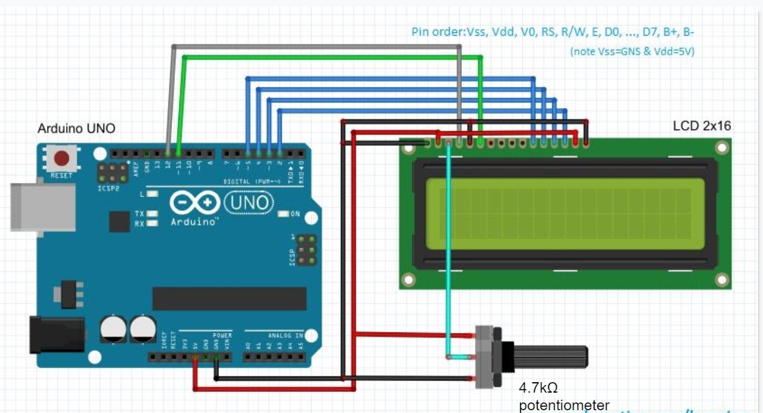
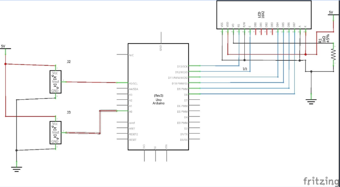
LCD
Why is the LCD used?
To display certain information or data on the screen. They are useful for debugging when you cannot use a laptop or serial monitor.
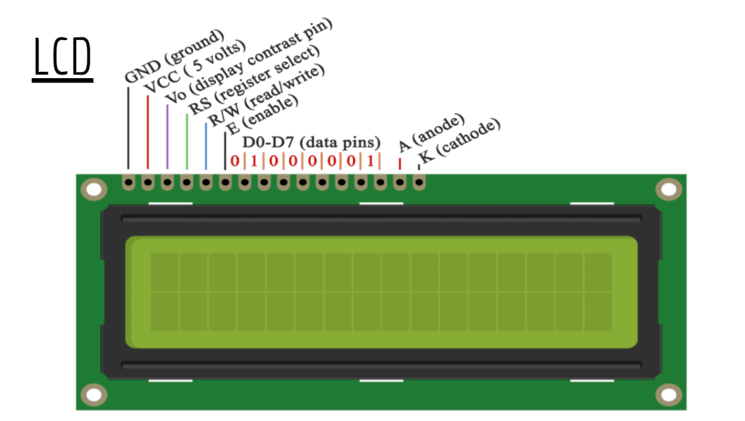
Functions:
- lcd.begin(16,2): This declares the size of LCD
- lcd.clear(): Clears the LCD
- lcd.setCursor(0,0): Moves the cursor to (0,0) of the array
- lcd.print(“hello world”): Prints whatever is in the bracket
Exercise:
Write code to display the distance directly onto the LCD
For more information visit : Liquid_Crystal_Library
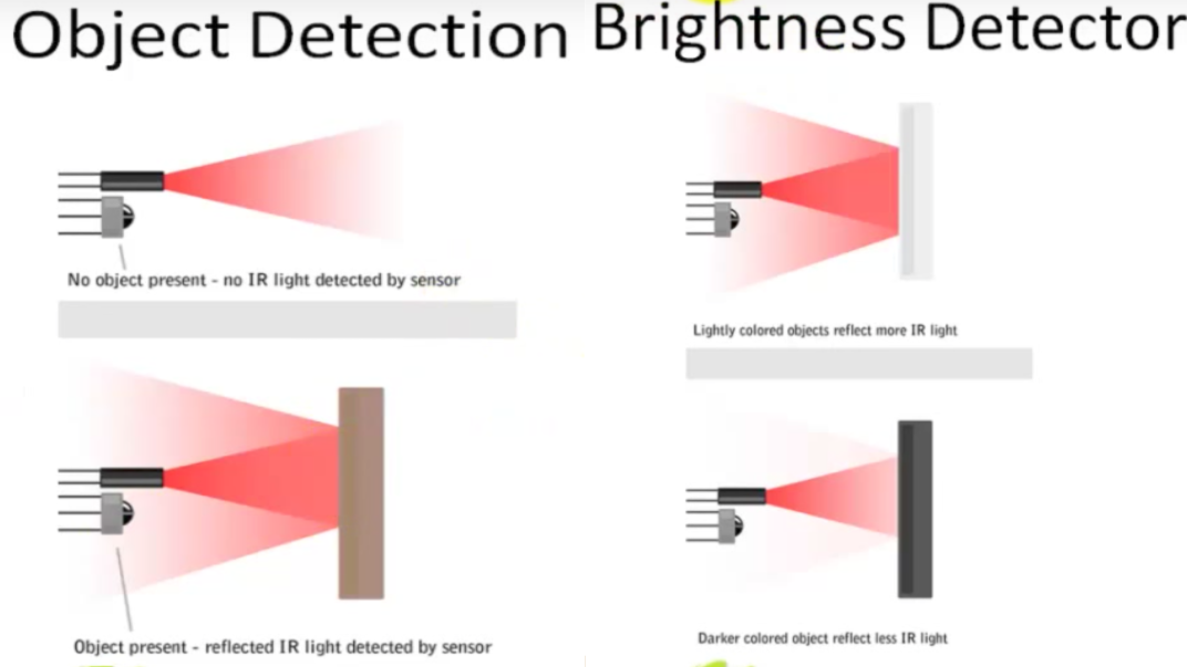
Infrared Sensor
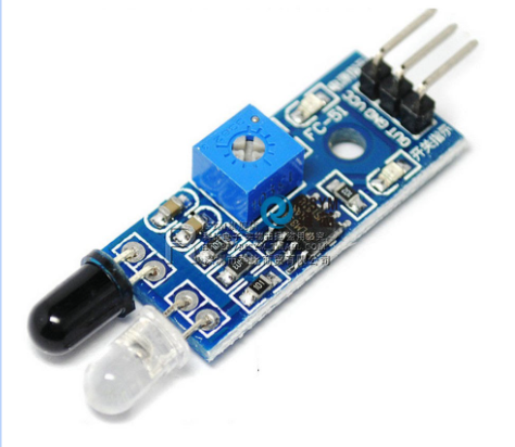
- I.R. sensor is used as a proximity sensor or collision sensor (not exact distance).
- TX which emits IR light continuously.
- So, when an object is near the sensor light is reflected into the RX which creates a voltage difference.
- The generation of this voltage difference depends on the intensity of IR light received by the RX
Note: You cannot use IR sensors outdoors or in bright lights because the IR light of the sun or from the bulb interacts with the RX. Use US sensors instead.
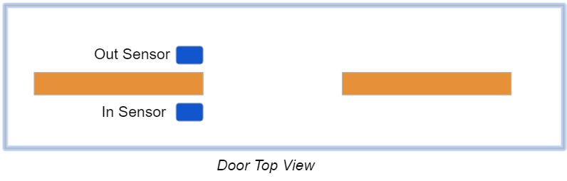
**IR Sensor People Counter
**To make a device which counts the number of people entered, excited and present in the room using an IR sensor.
Example
- For an Arduino UNO we can only send one byte at a time and hence we will communicate between the two arduinos using characters “H” and “L”. (We can do this using numbers as well)
- One Arduino will serve as a sender while the other will be a receiver. The communication will take place through the set of Serial() functions.
Bluetooth Module
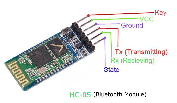
Here is our Bluetooth Module with its Pinout.
The Bluetooth Module will communicate with Arduino via Tx / Rx Pins (Pin1/Pin0) present on Arduino,as we used second Arduino in above communication.
Ps:We Only Need Vcc,Gnd,Tx,Rx Pins For Such Communication.
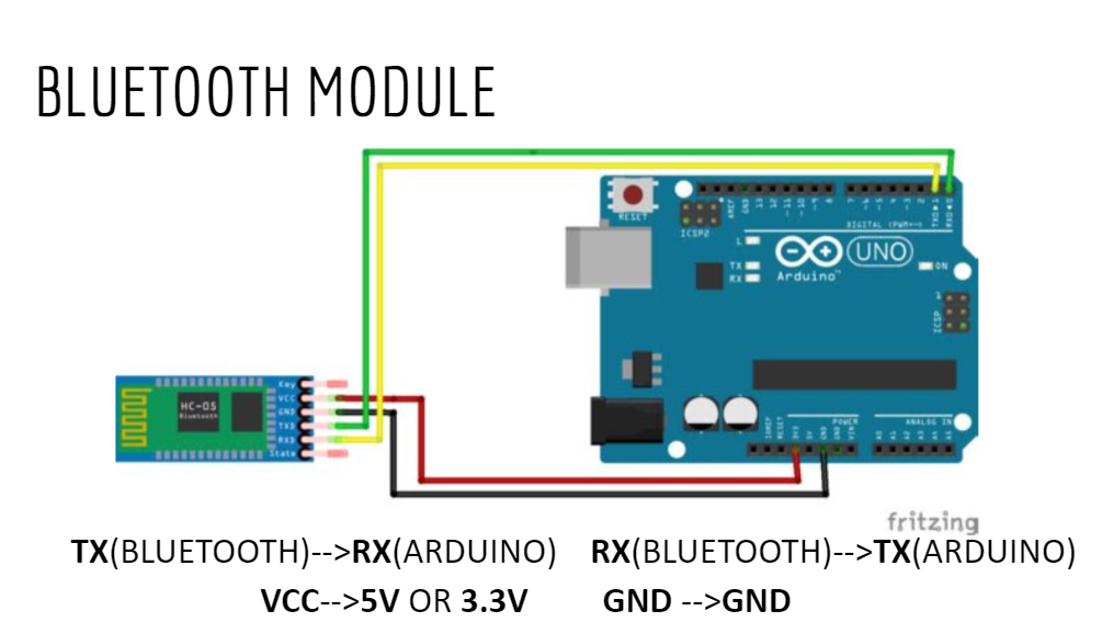
Arduino bluetooth basic tutorial: working on bluetooth module
Arduino Communication Protocols
Three Protocols for device communication :
- UART - Universal Asynchronous Receiver/Transmitter
- SPI - Serial Peripheral Interface
- I2C - Inter-integrated circuit
Details can be seen here : Arduino-communication-protocols